Mini Thunderbolt Siren Project

I got the wild idea to build this 1/6th scale model of a Federal Thunderbolt after I built a siren rotor and chopper stator as a "during break and lunch time" manual-lathe-practice project at work. I used a Radioshack 12 volt motor for the chopper motor just to see if it would work.
After building a single-tone 4 port rotor I had the idea to make a Mini-Thuderbolt out of it. I figured out the scale of the small chopper unit I had built at about 1/6th of the size of the real Thunderbolt siren so I could design the rest of the siren from there. The chopper is actually a bit too tall compared to a real Thunderbolt siren but after I had the chopper finished I didn't want to go back and redo it just because of that small scale error. Here is a description of the progress on the Mini-Thunderbolt as of January 2018.
My First YouTube Video Of The Mini-Thunderbolt Operating.
Link to my youtube channel. http://www.youtube.com/user/vanamonde2
Chopper, Stator, Upper Bearing And Horn Mount
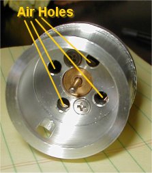 Stator Air Holes |
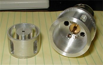 Original 4-Port Rotor With Stator And Motor |
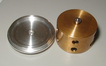 Brass Dual Tone Rotor With Upper Bearing and Chopper Housing Top |
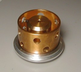 Rotor And Housing Top Together |
 Entire Unit Assembled Before Horn Mounting Boss Installed |
 Horn Flange Attached To Stator |
The size of the Radio Shack 12-volt motor dictated how large the chopper was going to be. The blower air actually goes through and around the motor and then through air holes in the bottom of the stator where the motor mounts. After these photos were taken I enlarged the air holes to allow more air to get through. The original aluminum single tone 4-port rotor is in the top two photos above.
My second chopper was a dual-tone (5/6 ports) and made out of brass (seen in the center two photos above). An upper bearing was added to stabilize the chopper because it was so much heavier than the first single tone aluminum chopper. I then ruined the brass chopper by filing the holes into rectangular slots. I thought that would allow more air through but all it did was throw the thing way out of balance which made for excessive vibration when running.
I later made another dual-tone (5/6 ports) chopper out of aluminum which was identical to the brass chopper but I left the holes round on the aluminum dual-tone version. You can just see the holes of the aluminum dual-tone chopper through the stator slot in the lower left photo above. This aluminum choper
Rotator, Chopper Housing And Horn

Here is an early photo of the Rotator and chopper housing tube with the chopper removed. The terminal block on the top is a temporary connection for the chopper motor brushes. The wires sticking out of the chopper housing are the wires to the chopper motor. The corner post at the rotator gearbox had to be omitted for the gearbox to fit.

Designing the rotator and chopper housing was by far the hardest part of this project. Since I built it at 1/6th scale I wanted to keep everything as close to scale as I could. The rotator box was scaled directly from my Thunderbolt siren that I restored. The trick then was to figure out a way to drive the rotator. I found online that Tamiya makes a gear box (Tamiya Item no. 70110) that has a 5000 something to 1 gear ratio resulting in an output shaft speed of about 2 rpm which is perfect for the Thunderbolt horn rotation speed. The Tamiya gearbox was an EXACT fit into the rotator box. The Tamiya gearbox allowed me to keep the location of the chopper air tube as it passes through the rotator box within .030" of the exact scale location. I only had to cut a few pieces off the plastic frame of the gearbox for clearance.
A set of pulleys was all I needed to make a belt-drive the rotator. A co-worker suggested the use of o-ring material as a belt. All I had to do was cut the o-ring stock to length to make the belt. Thanks Mike! For a bearing between the rotator tube and top and bottom plate I made some delrin bushings. Since the rotation speed is so slow simple bushings are fine. The upper plastic rotator bushing doubles as the insulator/mounting for the chopper motor brush collector ring set.
The horn is made out of plain old posterboard. I reduce-copied some scale drawings I made from a real Thunderbolt horn onto posterboard then cut out the pieces. Bending the pieces on the drawing lines to duplicate the bends on the real Thunderbolt horn resulted in an exact scaled down horn.
A plastic polystyrene flange glued to the horn end where it mounts to the chopper stator finised it off. When these photos were taken I still had to prime and paint everything. The horn is screwed to the stator boss with 0-80 screws. The horn support is made from polystyrene angle and mounts to the chopper housing and horn with screws just like the real siren.
Chopper/Rotator Exploded Parts View
Click Photo To See Larger

Blower, Air Pipe & Support
Click Photos To See Larger
 |
 |
 |
 |
The blower I was going to use originally was an electric A.I.R. "smog" pump from a Camaro. I abandoned that mess I came across an air mattress blower that runs on 120-volts and is far easier to deal with than the 12-volt smog pump blower which had to be run with a large 12-volt battery. Now using a small 120-volt AC to 12-volt DC power supply to supply 12-volts to the control circuit and chopper/rotator it's far easier to deal with.
The air mattress blower is mounted to an aluminum frame and a PVC air pipe is clamped to the frame. In the photos above the blue stuff is air filter material I put on top of the blower to cover the air intake of the blower. I built the blower frame end where the air pipe clamps on to look like the real Thunderbolt blower frame from the outside. The blower box is made of polystyrene plastic. With the 120-volt blower I moved the blower relay from the Mini-RCM panel to the inside of the blower box. This keeps the 120-volt all inside of the blower box near the 120-volt blower motor. See photo below.

Here is the blower hooked up. The 120-volt (big cord at bottom of photo) hooks up on one side of the blower and 12-volt control connection is on the other side of the board with the blower relay. The 12-volt control connects to the Mini-RCM panel board. (see below) This arrangement is so much better than the 12volt blower mess I had before. I had to run it off of a large 12volt battery because it pulled so much current. The finished siren will simply be plugged into a wall outlet now and a 12volt power supply will power the chopper, rotator and Mini-RCM control board.
My YouTube Video of the Mini-Thunderbolt Parts
This Video Was Done With The Original 12-Volt Blower
Mini-Thunderbolt Electrical Stuff
Click Photos To See Larger
 |
 |
The above left photo shows the 12-volt power supply (black) box, Mini-RCM panel/board and blower. The 12-volt power supply will power the chopper and rotator and the control circuit of the Mini-RCM panel/board. The blower will be powered by 120-volt wall current which is switched by the 12-volt relay on the blower circuit board. The Mini-RCM controls the blower relay as well.
The above right photo shows what will eventually be the lower enclosure box for the power supply box and bank of capacitors for the chopper circuit. The Mini-Thunderbolt siren will sit on top of this enclosure box. The bank of capacitors is wired in parallel with the chopper motor to allow the chopper to have a coast-up and coast-down like the full size Thunderbolt. Without the capacitors the chopper motor stops and starts as soon as voltage is switched on or off. With the capacitors in the chopper circuit the chopper coasts-up as the caps charge and coasts-down as the caps discharge when the chopper relay turns off. There is an electronic way of doing this but since the caps work I am going to keep it that way for now.
 |
 |
The two photos above show the Mini-RCM panel/board. In the original configuration the blower relay was also mounted on this board but now there are only the chopper and rotator control relays on this board. Those are the blue relays in the upper right corner of the board. This board also has a time delay circuit just like the real Thunderbolt siren RCM panel. I use a set of capacitors for the time delay on the Mini-RCM. The time delay is about 7 seconds which keeps the blower and rotator on after the chopper relay disengages just like the real Thunderbolt. The time delay capacitors are connected to the small black relay next to the blue chopper and rotator relays. This Mini-RCM panel/board will go into a 1/6th scale box enclosure (partially finished in the above right photo) and be mounted to either the Mini-Thunderbolt siren air pipe in a roof mount diorama type display or a 1/6th scale pole mount display. I haven't decided how I am going to finish it out yet.
THE ORIGINAL MINI-THUNDERBOLT!
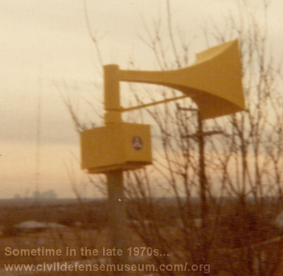
Sometime in the late 1970s I built a non-working posterboard, wood and plastic model of a Thunderbolt siren. I only have a few pictures of it. Actually, I had forgotten all about it until a few years ago when I was going through some old photos. I don't remember what scale I built it too but I got the dimensions from a Federal Signal siren catalog. From the photos it appears to be about the same size as my Mini-Thunderbolt. I did eventually rig it up to rotate with a backyard grill rotisserie motor. The motor was down in the base and a wood dowel was attached through the pole to the bottom of the plastic tube that made up the chopper housing. When the motor ran it turned the wood dowel which made the horn turn. I can't for the life of me remember whatever happened to this model.