Some Miscellaneous Thunderbolt Siren Information
| Warning Sirens Main Page | Thunderbolt Restoration | Chopper/Rotator Restoration |
| Blower Restoration | Thunderbolt Control Panel | Some Thunderbolt Information |
Here is some miscellaneous bits of information and photos I have collected about the Thunderbolt siren over the years. I orignally had this stuff included in my other Thunderbolt pages but I thought it would make more sense to just stick it all on one page by itself. It's just a bunch of stuff like differences in blowers, rotator boxes, RCM cabinets etc. etc.
Thunderbolt RCM Control Cabinets
 RCM1A Cabinet 1952 |
 RCM1B Cabinet 1959 |
 RCM1A Cabinet 1984 |
RCM Cabinet Photo 1952 Click Photos To See Larger
I found some old Thunderbolt siren photos on the Seattle Washington Municipal
Archives web site. Included in their vast array of photos is this 1952 RCM
cabinet photo. Since the Thunderbolt came out in 1952 this must be one of
the very first RCM cabinets made. This RCM panel is very different in arrangement than any other
panel I have ever seen (probably because it's one of the first RCMs) because the Blower starter is
at the lower left, the Rotator starter is at the upper right and the Chopper starter is at the
upper left. All the other standard RCM1s that I have seen have Blower starter at the upper left, Rotator
starter at lower left and Chopper starter at upper right. I have studied this photo over and over again and I can't figure out where the power
comes into and hooks up to the panel because there is no input power terminal strip or block. Everything
is hooked up in this photo except incoming power.
The Seattle Municipal Archives folks were kind
enough to send me a high resolution scan of the negative of this photo.
The photos of the Seattle Thunderbolt siren are on the Siren
Pictures page 2.
RCM Cabinet Photo 1959
This RCM1B cabinet was removed from Dallas Fire Station 33 just before the station was demolished in
2009. I called the demolition company and they gave me permission to remove the RCM cabinet and the
blower from the station property. I was supposed to get the chopper/rotator as well but that never
happened. The panel arrangement changed a bit from the early 1952 version and stayed very similar to this
arrangement for the rest of the Thunderbolt siren run. Notice there are no fuses in this 1959 model
RCM1 cabinet even there are two screw holes where the fuse block usually goes.
Mid-Late 1970s RCM1A Cabinet Photo
See the Thunderbolt Restoration Control Page to see a Mid to Late 1970s
version RCM1A control panel.
1984 RCM1A Cabinet Photo
This RCM1A cabinet was removed from Dallas Fire Station 10 just before the station was partially demolished
for an addition in 2009. I contacted the city and was able to remove the siren after the demolition
company removed it. The siren was then moved to Oak Ridge, Texas. This is the final arrangement of
the RCM1 cabinet as far as I know. It's still basically the same except a couple of fuses were added
to both legs of the rotator circuit and the Control, Rotator and Chopper terminal strips were
consolidated into one long single terminal strip below the chopper transformer. The Blower terminal
block was also moved over to the lower left to make room for this longer terminal strip. NOTE: The
small terminal strip next to the chopper transformer isn't orignal to this RCM panel. It was added
by the city to hook up a radio receiver.
RCM Cabinet For Thunderbolt 1003 Siren at LaGuardia Airport New York City, NY.

My observations about this unique RCM panel.
The above photo was sent to me by a
Mr. Guzman with Laguardia Airport in New York, NY in 2006. Mr Guzman
had some questions about their two 1003 Thunderbolt sirens that are located at the airport. This RCM
panel is of particular interest because I believe it was custom made for their unique application.
The building where this 1003 siren was located (not sure if the siren is still there) is on the west
end of the airport property on top of the Laguardia Learning Center building.
As far as I can tell from the photo the rotator on this Thunderbolt 1003
is set up for the horn to oscillate back and forth instead of doing a complete rotation cycle. This would
keep the rotation of the horn sound projector pointed into the airport property area.
The set of dual motor starter relays in the center lower part of the RCM panel is an Allen Bradley reversing motor contactor (relay). The reversing contactor alternately switches two legs of a three phase motor to switch the rotational direction of the motor as needed. One relay turns the motor clockwise and the other turns the motor counter-clockwise. The rotator motor on a Thunderbolt siren is the only motor that it would make sense to connect to a reversing starter. I can't imagine ever connecting a blower to a reversing starter and it wouldn't work with the chopper motor because it's single phase and it wouldn't matter which way it was turning anyway.
Mr. Guzman didn't send me any photos of the inside of the rotator but I believe that the rotator for this siren had two limit switches connected in some way to the rotator drive mechanism. The rotator would have to have two limit switches for this to work because the reversing starter would have to be switched back and forth when the horn reached it's rotational limit at each end of it's travel.
I can barely make out in the photo the label under the terminal strip at the bottom left. It looks to me like it says "ROTATE" and the rest of the label is illegible. I believe this is where the rotator limit switches connect. I have no idea what the relay next to the test switch panel could be used for but it's most likely part of the rotator reversing circuit. Also as far as I can tell from the photo the terminal strip at the upper right must be the "Control" input and I believe the chopper output is also on the same terminal strip. Evidently the lack of room in the panel eliminated the use of a pitch changing chopper transformer. The terminal strip at the center bottom of the panel is connected to the output of the reversing starter and the terminal strip has two heaters to protect for overload. That terminal strip just has to be the connection for the rotator motor.
All of this it what I have been able to figure out from the above photo. I may or may not be correct about the rotor having limit switches but I believe that's the only way this system could work automatically. I can't imagine someone sitting there switching the horn rotation back and forth manually as the siren operated.
Thunderbolt Siren Blowers
This blower information is based on the blowers I have presonally dealt with and information in Thunderbolt siern manuals. There may be some other differences in blowers out there that I haven't come across yet. There was indeed a gas powered Thunderbolt 2000 siren but I only ever seen a few photos of one but don't have permission to show them on this site.
A-Series Blowers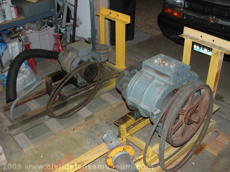

|

|
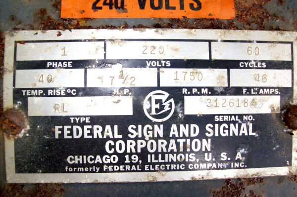
The above photos show the early type (larger Sutorbilt 6M?) and later type (smaller Sutorbilt 4M?) of Thunderbolt A-Series blower units side by side. The difference is obvious from the photos. Federal went to the smaller size blower in the 1960s. I don't know the exact year. The smaller blower runs at a much higher speed than the larger type. Notice the pulley sizes on each blower. When these blowers are running the smaller blower really screams while the larger just putt-putts along. The larger type blower unit is very heavy. I would guess it's well over 700 pounds with the motor on the frame. At the time this photo was taken I had the blower motors at the motor shop for a checkup before sending them to Moss Lake, Texas. Both motors were in good condition. Both of these blowers use 7.5 horsepower 240 volt 3-phase motors. Click smaller images to see larger.
 |
 |
The above left photo shows two older A-Series three phase blowers with the motors installed. The above right photo shows an older style A-series single phase blower. The old style single phase blower used a repulsion induction single phase motor which runs twice as fast as the three phase motor. Since the single phase motor runs faster the roots blower is half as large as the roots blower used on the three phase blower. I thought this would make a big weight difference in the blower but the single phase motor is quite a bit heavier than the 3 phase. The single phase blower still isn't nearly as heavy as the three phase unit though. The later model blowers use capacitor start single phase motors. Click images to see larger.
Old Single Phase Blower Photo From Bremerton Washington
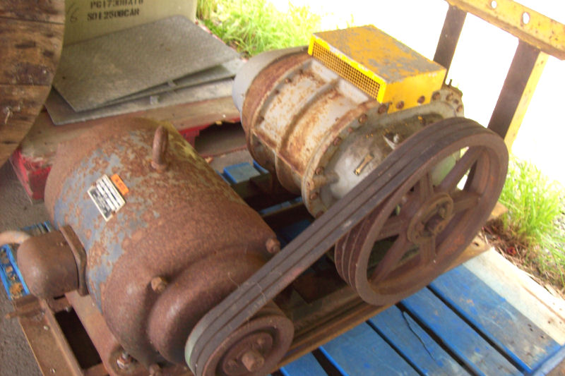
I received these photos via email in June 2013 about a blower that was up for auction in Bremerton Washington. I thought I would include these photos because I have never seen a single phase motor like this one. I don't know if it was sold or not. I really would have liked to get a chance to bid on it. I believe that the gentleman who sent me the photos said that there wasn't a blower cover with it.
B/C-Series Thunderbolt Blower.

|

|
The B-series Thunderbolt blower changed to a little different configuration and that configuration stayed the same with the C Series Thunderbolt. The B/C-series used a vertically mounted blower (Sutorbilt 4M?) with smaller double belts. These photos are of a blower removed from Dallas Fire Station Number 10 in March of 2009. The B/C Series blower is also very different from the A Series blowers in that the frame is far simpler and the blower cover box is quite a bit smaller than the A Series blower. Click smaller photos to see larger.
Water Treatment Plant Aerator Blower - Where The Thunderbolt Blower Came From
 |
 |
I thought I would add a few noteworthy pictures here of a small water treatment plant aerator blower. This blower is one of three at the Valley View, Texas water treatment plant. Looks a bit familiar doesn't it? Even the pressure releif valve in the above right photo is the same valve as a Thunderbolt except the weights are a larger diameter.