The First Siren Project
Federal Thuderbolt 1000 Restoration
| Warning Sirens Main Page | Thunderbolt Restoration | Chopper/Rotator Restoration |
| Blower Restoration | Thunderbolt Control Panel | Some Thunderbolt Information |
Thunderbolt Siren Chopper Motor
The chopper is the part of a siren that actually makes the noise. The chopper consists of a motor with a slotted rotor attached to the motor shaft. The slots in the rotor cause the air to be "chopped" into pulses as it passes through the openings when the chopper is spinning. A Federal Signal manual describes it as a "rotating air valve." All mechanical sirens work this way.
The Thunderbolt siren pumps a large volume of low pressure air through it's chopper rotor with the blower to increase the sound volume coming out the horn. The Thunderbolt 1000 chopper rotor is the same as the chopper rotor used in the Federal Model 2 siren. The single tone Thunderbolt chopper has 5 openings for air to pass through. This Thunderbolt 1000 that I restored is a single tone siren with with a rotor with one row of 5 openings. The dual-tone Thunderbolt chopper has 2 rows of slots. One row has 5 slots and one row has 6 slots. See a photo of a single and dual tone chopper here Federal Fire Signal Sirens.
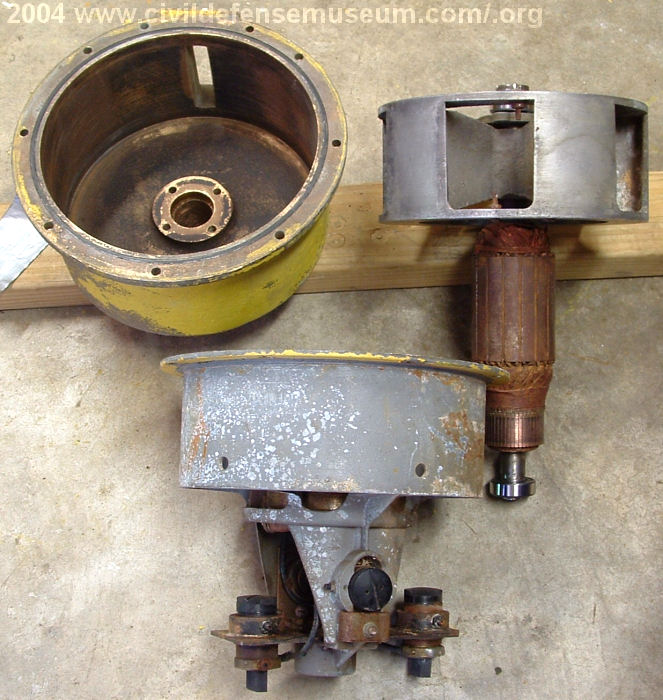
Here is the chopper assembly as it looks when it is removed from the Thunderbolt chopper housing tube. This photo was taken before I painted the chopper cap (stator) which still is in it's natural metal bronze color. The base of the projector horn attaches at the location of the slot in the bronze stator housing. The four bolt pattern around the slot in the cap is where the horn bolt attach to the chopper cap (stator).
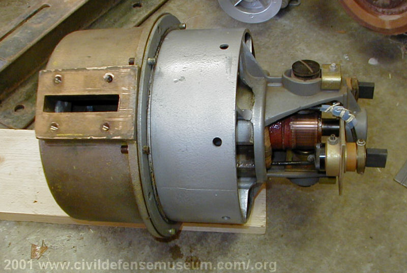
This Thundebolt model 1000 has a single tone chopper. The motor armature is visible through the motor bottom frame (large silver painted part of the assembly) to the right in the photo. You can see the copper bars of the commutator at the bottom of the motor armature. The black screw cap on the outside of the motor frame is one of the caps that the holds one of the two motor brushes in place. There is another screw cap on the opposide side of the frame for the other brush.
The series of holes spaced around the silver motor frame are bolt holes for the support legs when the bottom frame is used for a Model 2 siren. The bottom motor frame parts are interchangable between the Model 2 and other Thunderbolt sirens except for the very short-lived B-Series Thunderbolt which had a different chopper motor. The two black rectangular objects sticking out at the bottom of the motor frame on the right in the photo are the brushes which ride against the collector rings (see below) in the bottom of the chopper housing tube. As the chopper housing rotates these brushes carry the electric current from the collector rings to the chopper motor.
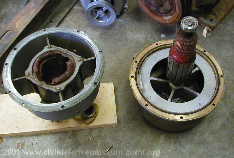
The first step in taking the chopper motor apart is to split the two halves of the chopper motor apart. The motor is held together out of the chopper tube by five taper pins which align the motor frame to the chopper cap (stator). The above photo shows both halves of the chopper motor pulled apart. You can see the top of the motor windings in the center hole of the motor frame on the left.
Here is a closeer look at the chopper in the stator/cap. You can see the bearing retainer through the 2 spokes of the chopper wheel. I had to repair the threads in this retainer with Heli-coils because they were stripped out. The stator reminds me of a brake drum from a car. The inside of the stator is turned on a lathe to allow minimal gap between the chopper and stator. You can see in the picture how close the fit is between the chopper and the inside of the stator. There is also a large o-ring seal around the bottom of bronze stator/cap to seal the stator against the motor frame face.
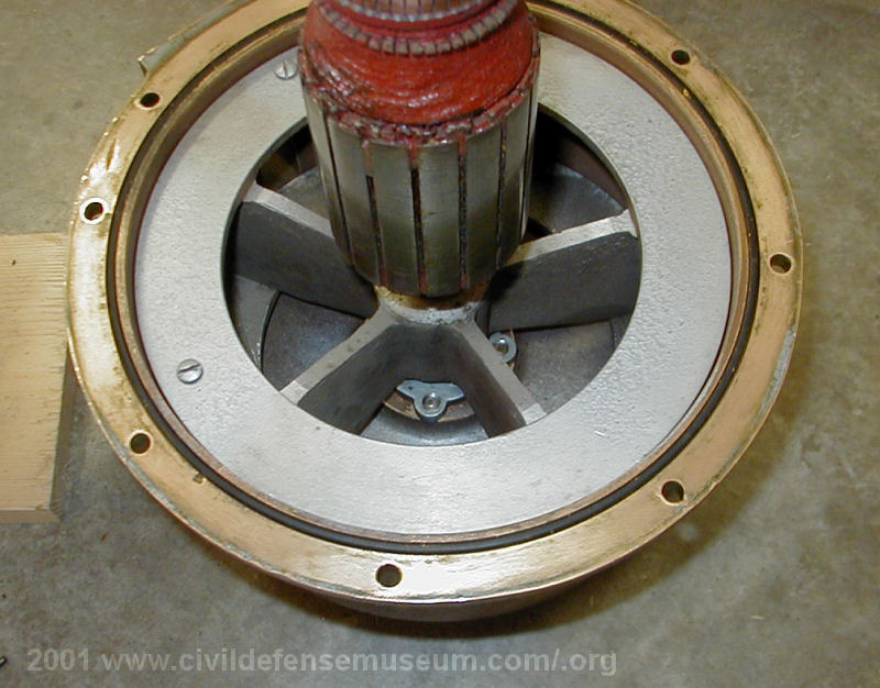
Here is a different single tone Thunderbolt 1000 chopper out of the stator housing. This chopper is from a siren belonging to the town of Valley View. It's identical to the single tone chopper in the first Thunderbolt I restored. I didn't have a disassembled view that chopper motor so I decided to use this photo of another motor. The five openings (ports) in the single tone chopper rotor of the Thunderbolt 1000 allow a little more air to pass through than the dual tone Thunderbolt sirens so the single tone siren is just a little louder that the dual tone models. Air from the blower pulses through these openings, through the slot in the stator housing and out through the horn as the chopper spins while the siren is running.
Thunderbolt Siren Chopper Housing
The chopper housing is the steel "can" that the chopper motor assembly mounts down inside of. The horn support bracket attaches to the bottom of the chopper housing tube. At the bottom of the chopper housing are the collector rings. The brushes on the bottom of the chopper motor frame ride on the collector rings to carry the current from the non-rotating part of the siren to the rotating chopper motor.
Here is the entire supporting structure of the chopper housing with the chopper motor mounted inside the chopper housing tube. The rotator cover sheet metal has been removed revealing the rotator mechanism inside.
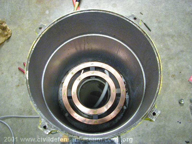
This is looking down into the chopper housing tube. The copper rings at the bottom of the tube are called collector rings. The chopper motor collector ring brushes ride against these copper rings as the chopper motor and tube rotate. I had always wondered how this was done but when I finally saw a Thunderbolt rotator taken apart I just thought "oh, yeah so that's how it works." You can see the chopper motor power cable passing down through the rotator support tube, though in this photo, it's not secured to the support tube with the cable retainer clip and the collector ring mounting bolts aren't installed yet. There is no danger of damaging the wiring when it's fully installed correctly because the tube and rings stay stationary while the housing rotates around it. The collector ring blocks bolt onto the center support air tube. The bolts aren't installed in this photo though. Also, the blower air comes up through this opening as the siren operates. Also note the four "blocks" evenly spaced around the outside of the chopper housing tube. These are the blocks where the chopper motor bolts go into to hold the chopper motor into the tube.
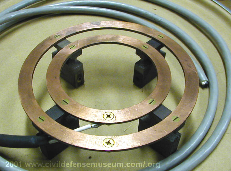
This is the chopper motor/rotator brush collector ring assembly. This ring bolts onto the rotator support tube that sticks through the bottom of the chopper housing. (see above) The brushes at the bottom of the chopper motor ride against these rings as the horn rotates. I had to replace the old rotten original wiring that connected to the rings. The wiring terminals were originally riveted to the rings with copper rivets. I replaced the rivets with screws and smoothed the tops so the brushes would ride smoothly over them. Later when I found out this siren would be going back into service I made some copper rivets and replaced the screws with copper rivets.
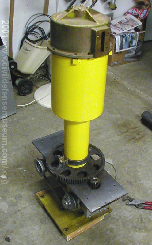
Thunderbolt Siren Rotator MechanismThe Thunderbolt siren uses a rotator mechanism to turn the horn. The rotator is a rugged design using a 1/3 horsepower motor, a standard type variable-speed belt pulley set-up, gear reducer, drive gear and driven gear to transfer the power from the motor to the chopper housing tube. I believe that this is actually a typical sign rotator mechinism adapted for use with the Thunderbolt siren.
I removed the sheet metal box from the rotator assembly so the inside can be clearly seen. The assembly is made up of the heavy steel bottom support section (still the original old yellow) that attaches to the top of the pole. The rotator motor and gear box attach to a 1/2 inch thick horizontal steel plate that bolts to the bottom support section. The pipe of the bottom support section is a single piece that passes through the steel motor plate. The large drive gear sets down in a recessed area in the steel plate. The belt is adjustable with slots in the motor mounting bracket and the speed of the horn is changed by moving the belt to the different pulleys. The horn rotation can be set to 2,4, or 8 rpm. The boss sticking up from the drive gear is where the drive band (explained below) clamps too.
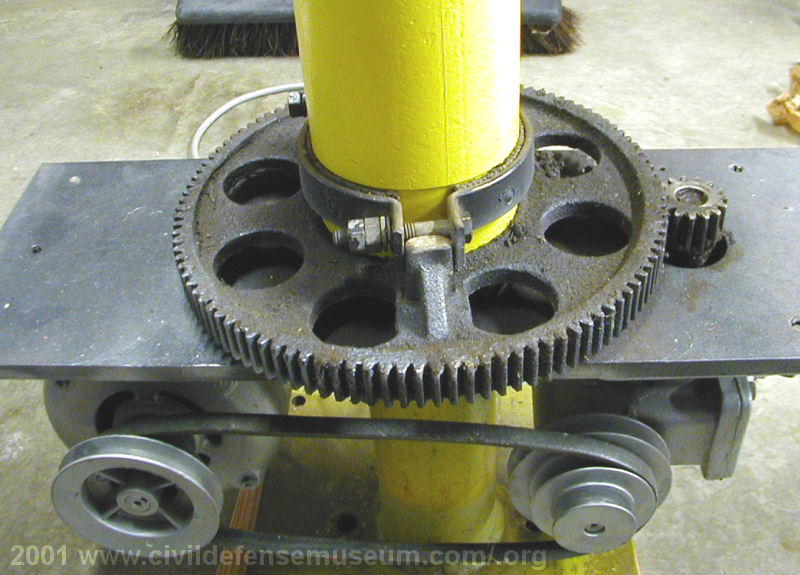
Here is closer view of the top of the rotator with the chopper housing installed. The chopper housing sits on top of a large driven gear. The driven gear attaches to the chopper housing with a wrap-around "drive band" clamp that allows the housing to slip under high wind loads against the horn. The drive band is clamped to a large boss that is cast into the top of the driven gear. On the other side of the drive band (view blocked by the chopper tube) is another bolt with a large spring so the clamping tension of the drive band around the chopper housing tube can be adjusted. A loose drive band will allow the horn to "slip" and turn on the driven gear more than a tighter drive band will. The Thunderbolt service manual says this is to avoid damaging the rotator mechanism by high wind loads. The drive gear that comes up from the rotator gear reducer is the small gear to the right.

Here is the other side of the rotator assembly. You can see the fitting that the chopper motor/collector ring wiring passes through just below the horizontal plate in the center of the bottom support tube. The wire from the collector rings in the chopper housing comes down through the center bottom support tube (see photo above) and out through this fitting for connecting to wiring in the rotator box. This fitting has a rubber seal and cap to keep the blower air out of the rotator box. Electrical hook-ups are on this side of the box away from the belt and pulleys. Obviously this photo was taken before any cleaning was done on the rotator parts.
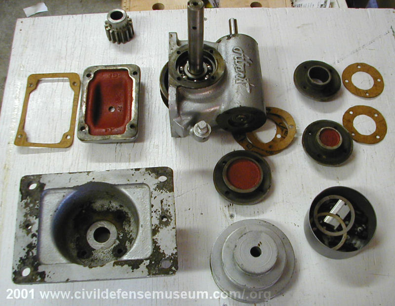
The Thunderbolt used an Abart 2-1/4ATD, 60-1 Ratio worm gear reducer for the rotator on the A and C series Thunderbolts. This reducer was leaking like crazy so I had to reseal it. I got a new input and output shaft seal and made new gaskets for it. I had to make new gaskets because evidently the gasket thickness comes into play with the adjustment of the gear reducer. I was going to simply reseal it with RTV silicone sealer in place of gaskets but when I bolted it together with only the RTV sealer the reducer locked up and wouldn't turn. Reassembling it with new gaskets allowed it to turn freely. This reducer was like new inside and showed very little wear. Even though this siren is more than 40 years old I guess it had actually probably seen very little use.
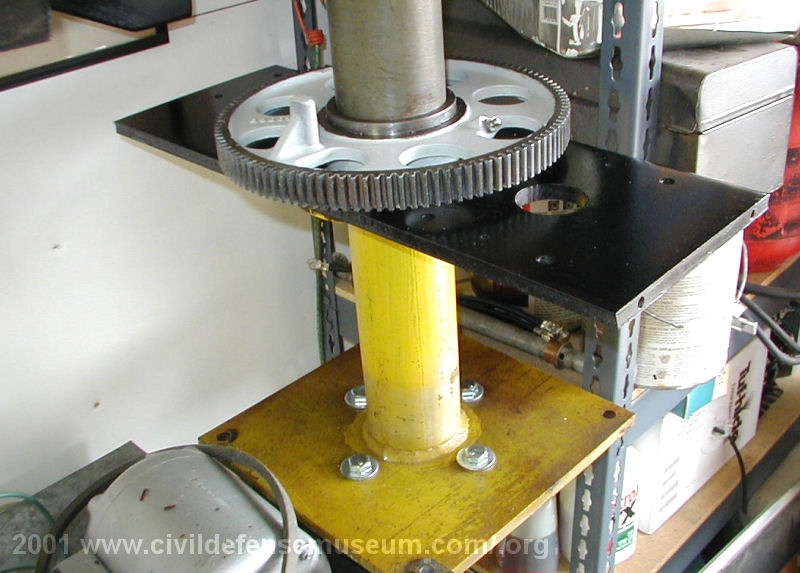
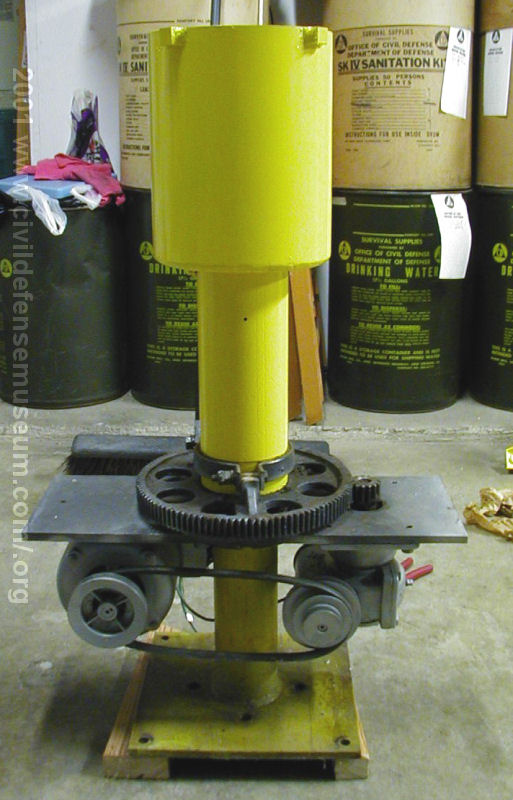
Here is the rotator bottom support, frame and gear before I put the housing back together. Everything is cleaned up and ready to go. I left the main rotator support it's original color. It took me about an hour to get the gear clean enough to repaint. That old grease was really coated on the gear. I installed a new single phase 240 volt rotator motor and belt when I completed the rotator assembly.

Here's the newly painted rotator, chopper tube and horn support. At this point everything but the chopper stator/cap and the blower box had been painted.
To finish off the entire chopper/rotator unit the horn and bracket were painted at Square Air in McKinney Texas by Mr. Danny Doyle. Using his paint equipment and paint booth. Thanks Danny!