
Thunderbolt Siren Restoration
Rotator
Thunderbolt Siren
Restoration Main
Siren Chopper
Chopper Housing
Rotator
Blower
Siren Controls
Sirens Main Page
Civil Defense
Museum Main
The Thunderbolt siren uses a rotator mechanism to turn the horn. The
rotator is very simple in design using a 1/3 horsepower motor and a
gearbox to transfer the power from
the pulleys to the rotator gear.
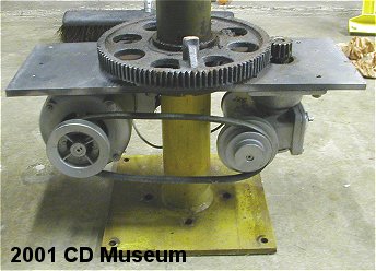 I
removed the sheet metal box from the rotator assembly so the inside can
be clearly seen in the pictures. The assembly is made up of the heavy steel
section (still yellow) that attaches to the top of the pole. The rotator
motor and gear box attach to a 1/2" thick horizontal steel plate that
bolts to the yellow section. The pipe of the yellow section is a single
piece that passes through the steel motor plate. The large drive gear sets
down in a recessed area in the steel plate. The belt is adjustable with
slots in the motor mounting bracket and the speed of the horn is changed
by moving the belt to the different pulleys. The horn rotation can be set
to 2,4, or 8 rpm. The boss sticking up from the drive gear is where the
drive band (explained below) clamps too.
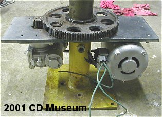 Here
is the other side of the rotator assembly. You can see the fitting that
the chopper motor wiring passes through just below the horizontal plate
in the center of the tube. This fitting has a pass-through rubber seal and
cap to keep the blower air out of the rotator box. Electrical hook-ups are
on this side of the box away from the belt and pulleys. This photo was taken
before any cleaning was done on the rotator parts.
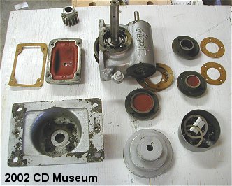 The
rotator gear box was leaking like crazy so I had to reseal it. I got a new
input shaft seal and made new gaskets for it. The thing is like new inside
and shows very little wear. Even though this siren is more than 40 years
old I guess it has actually probably seen very little use.
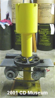 Here
is the rotator with the chopper housing installed. The chopper housing sits
on top of the drive gear. The drive gear attaches to the chopper housing
with a wrap-around "drive band" clamp that allows the housing
to slip under high wind-loads against the horn. The Thunderbolt service
manual says this is to avoid damaging the rotator mechanism. You can see
the drive band at the bottom of the housing tube where it clamps to the
gear. Click Photo To See Larger.
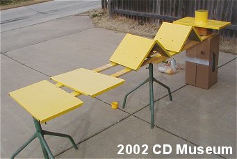 Here
are the parts of the rotator cover after painting. The rotator sheet metal
housing is in 5 pieces.
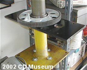 Here
is the rotator frame and gear before I put the housing back together. Everthing
is cleaned up and ready to go. I left the main rotator support it's original
color. It took me about an hour to get the gear clean enough to repaint.
That 30+ year old grease was really coated on the gear. I installed a new
single phase 240 volt rotator motor and belt when I completed the rotator
assembly.