Mini Thunderbolt
Project
Sirens Main Page
Back to Civil Defense Museum Main
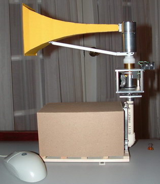
Chopper, Stator, Upper Bearing And Horn Mount
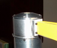
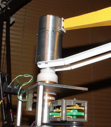
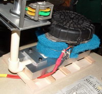
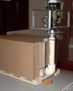
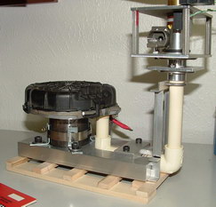
The size of the Radioshack 12volt motor dictated how large the chopper was going to be. The blower air actually goes through and around the motor and through air holes in the bottom of the stator where the motor mounts. Since these photos were taken the air holes have been enlarged to allow more air to get through. The original aluminum single tone 4-port rotor is in the top 2 photos below. I later made a brass dual-tone chopper (seen in the middle 2 photos below). I added an upper bearing to stabilize the chopper because it was so much heavier than the aluminum chopper. I then ruined the brass chopper by filing the holes into slots. I thought that would allow more air through but all it did was throw the thing way out of balance. I then made another dual-tone chopper out of aluminum which was identical to the brass chopper pictured below. You can just see the holes of the aluminum dual-tone chopper through the stator slot in the lower left photo below.
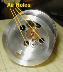 Stator Air Holes |
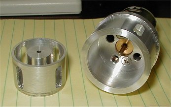 Original Rotor With Stator And Motor |
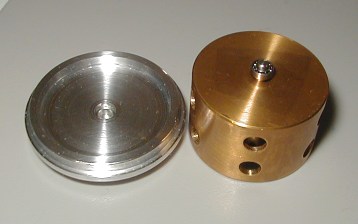 Brass Dual Tone Rotor With Upper Bearing and Top |
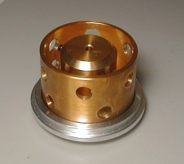 Rotor And Top Together |
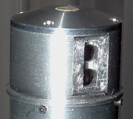 Entire Unit Assembled Before Horn Mounting Boss Installed |
Rotator, Chopper Housing And Horn
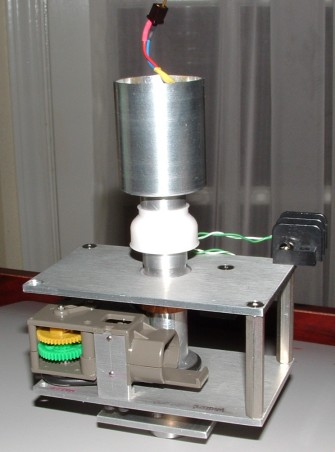
Rotator and chopper housing with chopper assy. removed. The terminal block on the top is a temporary connection for the chopper motor brushes. The wires sticking out of the chopper housing are the wires to the chopper motor. The corner post at the rotator gearbox had to be omitted for the gearbox to fit.
Rotator, Chopper Housing And Horn
Designing the rotator and chopper housing assy. was by far the hardest part of this project. Since I built the thing at 1/6th scale I wanted to keep everything as close to scale as I could. I scaled the rotator box from my real Thunderbolt and then tried to figure out a way to drive the rotator. I found that Tamiya makes a gear box that has a 5000 something to 1 gear ratio resulting in an output shaft speed of about 2 rpm which is perfect for the Thunderbolt horn rotation speed. The Tamiya gearbox was an EXACT fit into the rotator box. It was amost like Tamiya made the gearbox specially for this project. The Tamiya gearbox allowed me to keep the location of the chopper air tube as it passes through the rotator box within .030" of the exact scale location. I only had to cut a few pieces off the plastic frame of the gearbox.
I made a set of pulleys to belt-drive the thing with an o-ring after a coworker suggested that I use o-ring material as a belt. The rotator has a plastic bushing at the top and bottom of the air tube where it goes through the rotator. The upper plastic bushing doubles as the insulator/mounting for the brush collector rings.
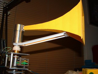
I made the horn out of posterboard. I copied scale drawings I did from the real Thunderbolt horn onto posterboard then cut out the pieces. I bent the pieces on the drawing lines to duplicate the bends on the real Thunderbolt horn. I glued a styrene flange on the horn end where it mounts to the chopper stator. In these photos I still have to prime and paint the horn. I made it out of yellow posterboard it's not painted yet. The horn is screwed to the stator boss with 0-80 screws. The horn support is made from styrene angle and mounts to the chopper housing and horn with screws.
Blower, Air Pipe & Support
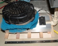
The blower is an electric AIR "smog" pump from a Camaro. It's the closest thing I could find that would fit in the blower box and still have a decent air volume output. It's similar to a vacuum cleaner motor. It's a bit loud but I'll use it until I come across something better that will fit in the blower box. The blower is mounted to an aluminum frame and the PVC air pipe is clamped to the frame. In the photos below the blue stuff is air filter material I wrapped around the blower motor. The air intake is right next to the outlet where the PVC pipe goes into the blower motor. I built the blower frame end where the air pipe clamps on to look like the real Thunderbolt blower frame from the outside. I still have to build the blower box. The blower box in these photos is the temporary cardboard box.
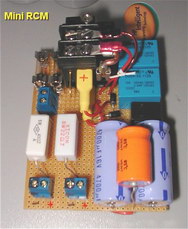
Electrical Stuff & Brushes
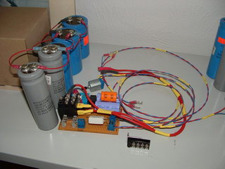
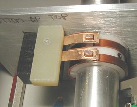 Brushes & Collector Rings Before wiring installed. |
